Description
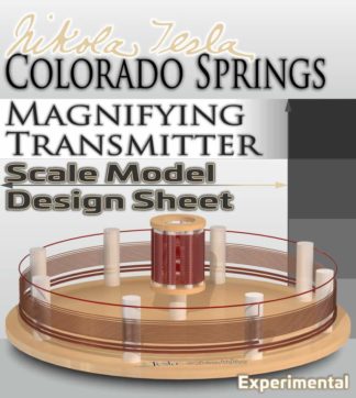
Build the world’s most advanced Tesla coil with the Colorado Springs Magnifying Transmitter Scale Model Design Sheet
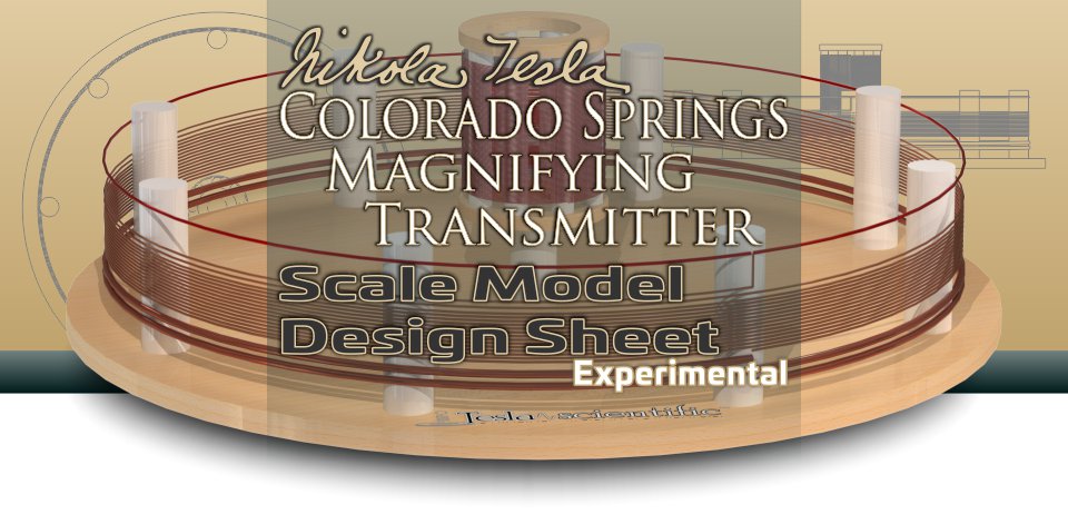
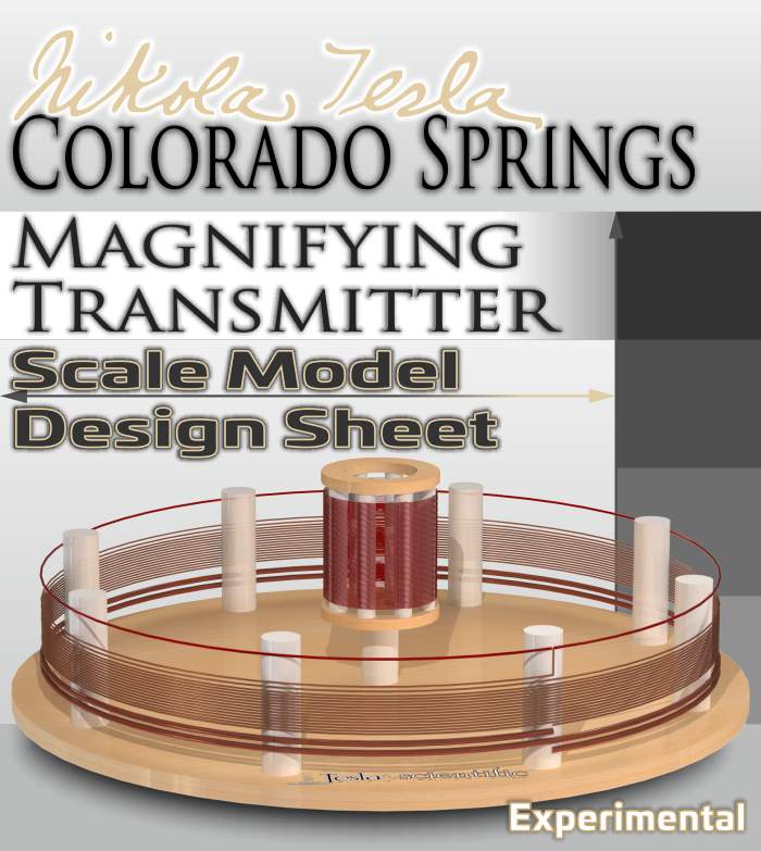
Designed by none other than Nikola Tesla himself through the extensive experimental research described in ‘Nikola Tesla: Colorado Springs Notes, 1899-1900‘, the Colorado Springs Magnifying Transmitter has now been scaled down to the finest detail, and is 100% functional!
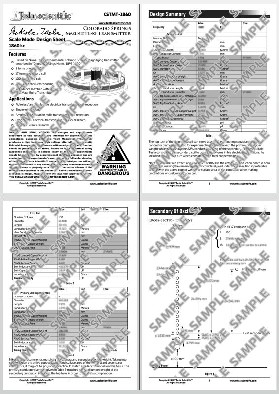
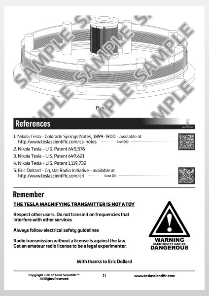
This downloadable 21 page PDF document includes 33 diagrams and pictures illustrating the scaled down Magnifying Transmitter design with fully detailed dimensions and circuit diagrams you can use for setting up your own experimental Tesla Magnifying Transmitter transmitting station, making it ideal for learning what Nikola Tesla was REALLY doing the best possible way – through direct experience.
IMPORTANT NOTE: You may find some coil designs to be excessively large, or excessively small, depending upon the facilities that are available to you. Please make sure that you can accommodate and/or build a Magnifying Transmitter of that size before placing your order.
Although the coils can produce sparks that would make any other comparatively sized ‘Tesla coil’ with a thousand more turns pale in comparison, these coils are optimised for the true method of wireless transmission of electrical energy for practical applications.
The Colorado Springs Magnifying Transmitter Scale Model Design Sheet offers the opportunity to go beyond merely making sparks for entertainment and visual effect, and delve deeper into the world of practical applications that Nikola Tesla envisioned for his wireless system, through being a consistent and verified design that’s sure to work as planned. Tip: If you and your friends all built coils that are designed for the same frequency, you could start your own experimental global communications network!
The coils may be small(-ish!) in size, but make no mistake, they are not to be taken lightly and should not be underestimated! For every volt input, you’ll get the same voltage step-up transformation ratio as the original full size Magnifying Transmitter due to the fact that the impedance of the scale model coils are matched to those of the full size Magnifying Transmitter. These coils are the real deal.
Custom designs are also available!
Order a tailor-made Magnifying Transmitter Scale Model Design Sheet for any frequency between 200 kc and 5000 kc (200kHz-5MHz)
Colorado Springs Magnifying Transmitter Scale Model Design Sheet Features
- Downloadable PDF – 21 pages, 33 diagrams
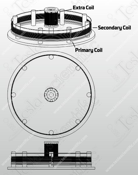
- 2 turns primary coil (experimental)
- 16 turns secondary coil
- 100 turns extra coil
- Impedance matched scale model – The coils are impedance matched with the full size Magnifying Transmitter – 1:1 scale voltage transformation ratio
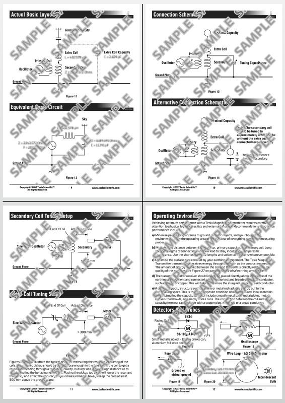
- Circuit schematics – Basic wireless transmission circuit diagrams to get you started
- Test setup diagrams with probes and detectors – Tools and procedures you can use for tuning and measuring your Magnifying Transmitter
- Secondary coil tuning frequency – The optimum tuned secondary coil frequency (experimental)
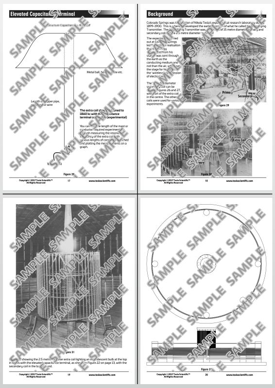
- Required elevated terminal capacitance – The amount of capacitance you’ll need to tune the extra coil to the optimum frequency (experimental)
- 62% ideal conductor spacing – The design sheet includes the ideal conductor diameter based on a 62% spacing factor, and suggests the closest available match for both SWG and AWG (secondary and extra coil)
- Conductor data – Conductor surface area, lumped copper weight, and active copper weight for the suggested conductors are included
- Matched copper weights – The primary and secondary conductor lumped copper weights are matched as closely as possible (not available for frequencies below approximately 450 kc)
- Coil electrical characteristics – Self-inductance, self-capacitance and impedance of the coils
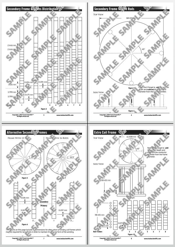
- Alternative coil frames – Diagrams, dimensions and groove spacing for secondary coil frames with 8, 12 and 16 rods allows you to choose which configuration best suits your needs
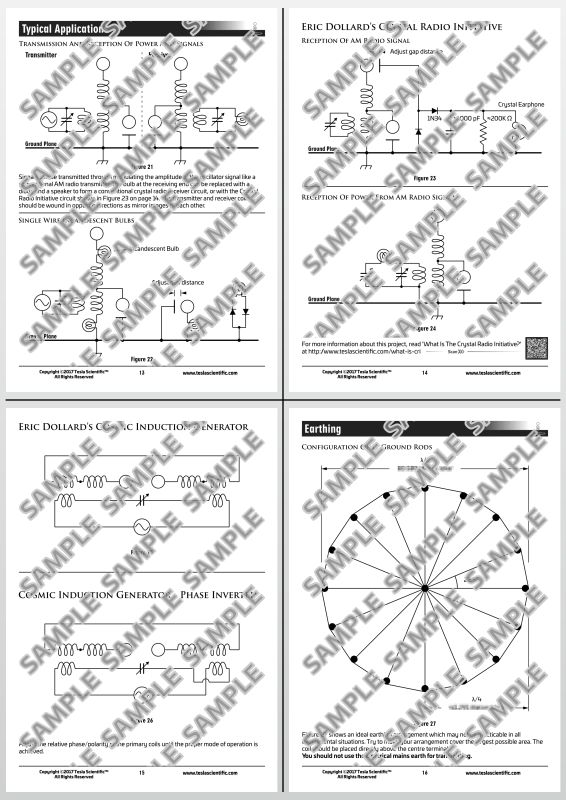
- Diagram showing the ideal earthing arrangement for the given design frequency
- Tips and suggestions for optimising the operation of your Tesla Magnifying Transmitter – The environment in which you are operating your Magnifying Transmitter is important. Learn how to maximise efficiency and avoid false readings
- Custom designs available – Order a tailor-made Magnifying Transmitter scale model design for any frequency between 200 kc and 5000 kc (200kHz-5MHz)
Applications
- Suitable for all ‘wireless’ and single wire electrical transmission and reception experiments
- Single wire lighting – Recycle and make full use of exhausted fluorescent tubes, or get adventurous and light up incandescent bulbs and more with only one wire! Delve even deeper and research the production of radiant energy like Tesla describes in U.S. Patent #685,957
- Amplitude Modulation radio transmission and reception – Communicate with your friends over distances much greater than is possible with conventional radio technology!
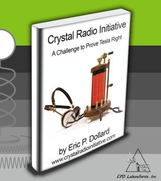
- Crystal Radio Initiative – 100% compatible with Eric Dollard’s Crystal Radio Initiative for receiving power through the earth from a local AM radio broadcast station (diagrams included)
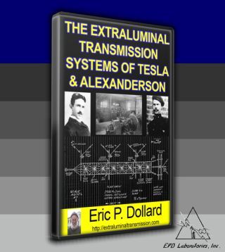
- Longitudinal electrical transmission network research – For a complete introduction into this subject, there’s a presentation given by Eric Dollard at the 2014 Energy Science & Technology Conference available here: The Extraluminal Transmission Systems Of Tesla & Alexanderson (also see this video on youtube)
- Cosmic Induction Generator – Produce novel electrical effects when two mirror image Magnifying Transmitters are configured as Eric Dollard’s ‘C.I.G.’ (diagram included)
- Telluric currents research – Study the electrical activity and natural signals occurring within the earth
Which design frequency to order?
Which frequency to use depends on what you would like to use your Magnifying Transmitter for.
Preset frequencies
The preset frequencies are suitable amateur radio bands which allows for the opportunity to legally experiment through getting an amateur radio license. This is ideal because simple circuits can be used to transmit and receive in order to communicate with others just like normal radio, and will surely help to prove that Nikola Tesla was right! A global network of experimenters using a common frequency could be the beginning of the practical realisation of Tesla’s ‘World System’ as he had envisioned over 100 years ago.
Custom frequency
A custom frequency is ideal if you would like to receive AM radio signals from a particular station as in Eric Dollard’s Crystal Radio Initiative or if you have a specific experimental frequency in mind, but you should avoid frequencies that coincide with existing services if you plan to use the coil to transmit.
You can use any frequency if you’re not transmitting, which means not connecting your coil to the earth. For ‘local’ experiments like this, a wire, or some other conducting medium such as an isolated bucket of garden soil or compost, can be used to simulate the single wire or ‘wireless’ transmission of power between the coils. You can also configure your coils to operate as Eric Dollard’s Cosmic Induction Generator which will not transmit energy.
Note: Very small high frequency coils can be tricky to build accurately due to the very fine tolerances. The order form will tell you the approximate diameter of the coils when you type in a custom frequency.
How to power the coils?
The recommended method of powering your Magnifying Transmitter is with a sine or square wave oscillator and a power amplifier. A sine wave oscillator is essential for testing and accurate measurement of your coil as it allows for precise tuning, and will allow for the transmission or clean audio signals. Spark gap transmission is illegal and should be avoided for transmitting signals due to the amount of interference caused not only to your own signals, but to every other radio signal in the area too. If you would like to experiment with spark gaps to see how big your lightning bolts can get, you should disconnect the Magnifying Transmitter from the earth and connect it to an isolated virtual ground in order to avoid illegally transmitting.
IMPORTANT SAFETY AND LEGAL NOTICE:
The designs and experiments illustrated in the Colorado Springs Magnifying Transmitter Scale Model Design Sheet are intended for experimental and educational purposes only.
The Tesla Magnifying Transmitter transmits electrical energy through the earth, and there may be an excessively high potential at the elevated capacitance terminal or free end of the coil. In application and for legal purposes, it should be considered as a radio transmitter which has the capability of disrupting radio transmissions, and damaging or destroying nearby electrical appliances.
Caution should be practised at all times. Failure to follow electrical safety guidelines may result in serious injury or death. All experiments should be supervised by a professional electrical engineer and are conducted at the experimenter’s own risk with a full understanding of the danger.
Tesla Scientific™ and any associated parties referred to or referenced in any way will not be held responsible for any consequences, injury or damages caused to any persons or property as a result of the use or misuse of the information contained in this document.

The Tesla Magnifying Transmitter should NEVER be deliberately misused
Respect other users. Do not transmit on frequencies that interfere with other services
Radio transmission without a license is against the law
Get an amateur radio license to be a legal experimenter


Reviews
There are no reviews yet.