How To Use The Crystal Radio Initiative Calculator
Free and Advanced versions
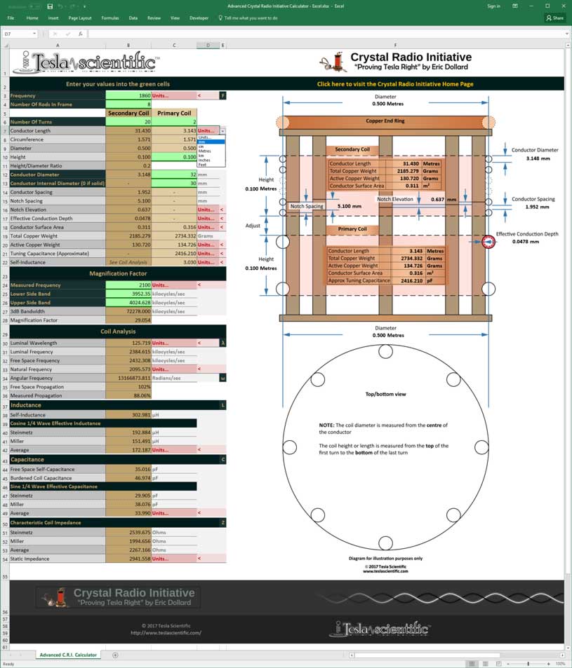
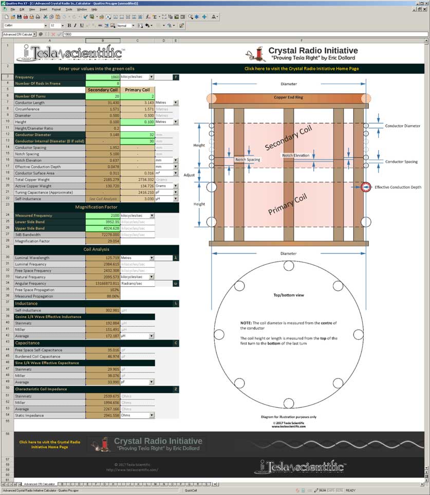
This guide will help you understand some of the features of the Crystal Radio Initiative Calculator. The information applies to both the Free and Advanced versions.
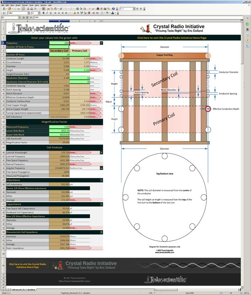
All the data that you need to input is entered into the cells with the green background.
Secondary Coil
Frequency: The most important number you need to input is the frequency. This should be the frequency of the AM radio station that you want to receive and it sets the physical size of the coil. You can also build a set of coils on amateur radio frequencies, but you need an amateur radio license in order to transmit.
Number Of Turns: The default number of turns is 20. A higher number will make the coil smaller at the expense of some performance.
Number Of Rods In Frame: This value is required for calculating the notch elevation. The rods have notches cut into them to keep the conductor in place. Bigger coils may need more rods to maintain the circular form of the winding. Try not to make a polygon.
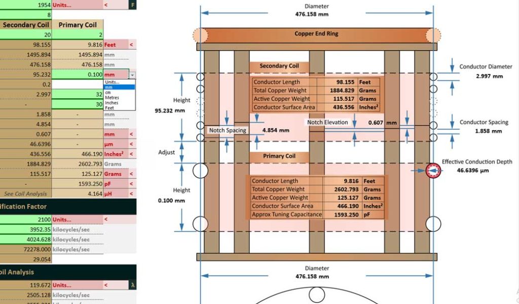
Notch Spacing: This is the space between each notch along a single rod, and the space between each turn of the conductor. The notches hold the conductor in place.
Notch Elevation: The notch elevation is the amount that the notches that support the conductor need to be shifted up on each consecutive rod of the frame, so that the conductor spirals around and ends up at the correct spacing at the beginning of the next turn.
Primary Coil
As Eric Dollard says, the primary coil is a complication that has to be experimented with. In general the primary coil consists of 2 turns and can be the same height as the secondary coil, or having the same amount of copper weight in total as the secondary coil. Matching the active copper or surface area may not be practical. The conductor spacing should ideally be 62% the conductor diameter.
Number Of Turns: The default number of turns is 2. A small number of turns yields a smaller inductance and requires a larger capacitance to be tuned to resonance. Increasing the number of turns increases the inductance and reduces the amount of primary tuning capacitance required.
Height: Choose your primary coil height/length. According to Eric Dollard the primary coil height should equal the secondary coil height, but this may not be practical in your construction.
Conductor Diameter: Choose your primary conductor diameter to match either the copper weight or surface area with the secondary conductor.
Conductor Internal Diameter (Advanced Calculator only): This is used for calculating the total copper weight when a hollow conductor is used and is optional. This factor doesn’t affect the active copper weight.
Magnification Factor
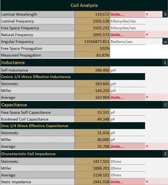
Measured Frequency: The frequency at which the output is at its highest. This is the resonant frequency of the coil.
Lower Side Band: The Lower Side Band is the lower frequency at which the measured output is 70.7% the peak resonant measured output.
Example: At a coil resonant frequency of 1860 kc and with a peak measured output of 100mA, tune the oscillator frequency down until 70.7% of the peak measured output value is reached = 70.7mA
The corresponding frequency is the Lower Side Band frequency.
Upper Side Band: The Upper Side Band is the upper frequency at which the measured output is 70.7% the peak resonant measured output.
Example: At a coil resonant frequency of 1860 kc and with a peak measured output of 100mA, tune the oscillator frequency up until 70.7% of the peak measured output value is reached = 70.7mA
The corresponding frequency is the Upper Side Band frequency.
Click here to find out more about the Crystal Radio Initiative, or visit the official Crystal Radio Initiative discussion on Energetic Forum.

